
Define Slopes - Bench/Lift Overrides
To access this screen:
-
Design ribbon >> Pit Modelling >> Design Slopes. Select the Bench Overrides tab.
-
Design ribbon >> Dump Modelling >> Design Slopes. Select the Lift Overrides tab.
Note: This panel is used for the definition of both pit and dump slope and berm width bench constraint settings. Unless otherwise stated, the terms pit and dump are synonymous, as are bench and lift.
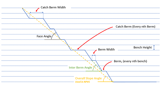
This panel allows the default to be set for each bench or lift. In the drop-down list, when a slope region has been defined, the Face Angle, Berm Width and (if specified) the Inter-ramp Angle of that region are used. The Berm Type determines which berm width is used.
Override rules are defined for each region independently.
For each region (including the DEFAULT region, as specified on the Define Regions screen) you define rules, per bench or lift (selecting from those already defined as part of the Define Benches or Define Dumps task), or set a rule for multiple (typically non-consecutive) benches or lifts in order to control the geotechnical slope design on a pattern basis. Another option is to use a manual specification, or any combination of these methods.
For example, you can define slopes using logic such as "after every 2 lifts, set a berm width to 18m but for every successive 4th lift, set a catch bench of 25m other than for benches 2120m and 2130m as they require a 30m lift and 20 degree face angle". You could also, say, remove berms using a rule such as "every 3 benches, set 2 benches to a berm type of NONE". The output of these choices is reflected in the table below, which can be modified further as required, even down to individual bench level.
You can define bench and lift constraints in either a top-down or bottom-up direction.

As with all managed tasks, updates made on this panel are committed to your project using the Save (1) or Save and Close (2) buttons at the top of the form. You can also Close without saving (3).
For example, the diagram below shows a cross-sectional view of a pit wall where a berm has been specified for every 2nd bench and a catch berm for every 3rd bench:
To define bench or lift overrides for a pit or dump:
-
Display the Bench Overrides or Lift Overrides screen.
-
Pick the Region for which override values are required. This can be the DEFAULT region or any region defined on the Define Regions screen.
Note: For any region other than DEFAULT, you can use Match <DEFAULT> . This means that regional overrides for the defined region will be the same as for the default region. Deselecting this check box enables the table below, letting you define region-specific overrides on a per-bench or per-lift basis.
-
To provide custom overrides for one or more benches on a non-default region, uncheck Match <DEFAULT>.
-
Choose the upper and lower bench to which overrides apply (essentially the elevation constraints) using From benchand To bench. Only benches within this inclusive range can provide override values.
-
Within the range set above, define the pattern of bench types (and associated face angles and berm widths) down the pit (or up the dump). Do this using these controls:
-
every – Select the interval (gap) between benches. For example, to set every other bench, "2" is appropriate.
-
bench(es), set – Choose the number of contiguous benches to set to a particular type, angle or berm width.
For example, if you were planning to set a catch bench every 4 benches with a berm width of 22 meters and a face angle of 35 degrees, every should be "4" and bench(es), set should be "1" (you are only creating a single catch bench every 4 benches.
-
-
Choose the Berm type to create using your bench pattern. This can be one of the following:
-
None – Set the berm width to zero for each generated bench.
-
Standard – Use standard berm width and angles from the region defined on the Define Pit/Dump Regions screen.
-
Catch – As above, but use the catch berm width and angles from the defined region.
-
Custom – Define your own Face Angle and Berm Widths to add to the overrides table.
-
-
Click Update generate bench override definitions in the table below.
Note: Existing records are only overwritten if they match the pattern set. Other benches are unaffected. This lets you define benches in batches and within different elevation ranges, for example.
-
Review and edit the contents of the table below. All fields other than Bench ID are editable:
- Bench/Lift ID – Each table row references a currently-defined bench or lift label (created as part of the Define Benches task). This is the scope of the override, if you like. You can't edit this cell.
-
Berm Type – Choose the type of berm for each bench level.
-
Face Angle – This can be used to define the face angle for the bench, where it falls within the specified Region.
-
Berm Width – This can be used to define the berm width for the bench, where it falls within the specified Region.
Note: Where a bench or lift isn't assigned to a particular slope region, the default region specification will be used but only if no Bench Fallback is provided.
-
Save your task settings using the in-screen toolbar.
Related topics and activities: